vacuum throttle body diagram
Wrap the end of the fuel line with a clean lint-free cloth. Avionics a blend of aviation and electronics are the electronic systems used on aircraftAvionic systems include communications navigation the display and management of multiple systems and the hundreds of systems that are fitted to aircraft to perform individual functionsThese can be as simple as a searchlight for a police helicopter or as complicated as the tactical system.
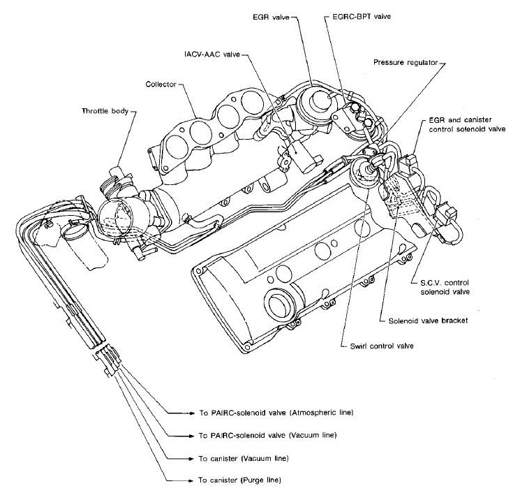
91 94 240sx Vacuum Diagrams Component Locaters
Symptoms of a vacuum.

. 10A Engine management Throttle body Wastegate valve Clutch pressure regulator F9 5A 15A Glow plug control unit fuel pump relay. A compressor a condenser a metering device or thermal expansion valve also. F14 5A Engine management main.
Display Modes 1 08335inAl. We carry a large selection of performance fuel injection systems and fuel injection parts to help you increase horsepower and make repairs. 1984-85 25L engine vacuum diagram throttle body injection Fig.
In most cars a mass airflow sensor is installed at the air filter box see the diagram. Must contain at least 4 different symbols. Intake manifolds and gaskets.
1984-86 28L engine 49 state vacuum diagram manual transmission Access our Jeep Wagoneer-Commando-Cherokee 1984-1998 Vacuum Diagrams Repair. Our HPFP kit comes with everything you need to replace your failing unit. Replace 4 wheel drive vacuum actuator 1998 dodge ram 1500 4wd 4x4 duration.
Accessory power outletRetained accessory power. Engine air induction system diagram. Rocket engines are reaction engines producing thrust by ejecting mass rearward in accordance with Newtons third lawMost rocket engines use the combustion of reactive chemicals to supply the necessary energy but non.
Hello here is a vacuum line diagram click the image below. And just terminates with this bung on the end around the right hand side of the throttle body. Vacuum canister delete Thread Tools.
Mk2 GTI vacuum diagram. C_a_r_t_e_r Jan 26 2007 18. Figure 1 depicts a typical single-stage vapor-compression system.
Throttle body diagram chevy injection s10 tbi repair system injector gm guides dual autozone guide wiring list fig firebird camaro. Code P0446 is set when the cars computer believes either correctly or incorrectly that theres a problem with the vent valve. In fact it was the founders Brian Ken Murphy that designed and developed the first aftermarket air intake systems performance throttle bodies for the then newly fuel injected 50L Mustang and TPI Camaro models.
Discussion in Engines started by md119 Mar 2 2006. Page 1 of 2 1 2 Next MD119. Accessory power outlet battery.
Disconnect and label all vacuum lines to the carburetor noting those lines that run from the distributor spark delay valve temperature sensing valve EGR valve fuel vapor canister and so forth. As such in some cases parts that might surprise you can trigger the code. Diagram f150 vacuum ford 97 wiring need ranger engine wire 2002 location.
ASCII characters only characters found on a standard US keyboard. Or at a throttle body it can cause a vacuum leak too. Used tuk tuk for sale usa.
6 to 30 characters long. All such systems have four components. 19 20 22.
Vacuum diagram ford 150 hose line lines system 1993 1989 mustang 1990 routing hoses efi questions there wiring px source. McMaster-Carr is the complete source for your plant with over 700000 products. Accessory power outlet 1Cigarette lighter.
Most systems have flaps or butterfly valves inside the manifold that vary the runner length. Propulsion transmission is the mode of transmitting and controlling propulsion power of a machine. 10-13 Chevrolet LS3 62L.
Body control module 3. Remove the existing carburetor by the. There are many different variable intake manifold designs in use today.
The BBK brand has been synonymous with bolt on performance for the modern muscle car since its beginning in 1988. F12 5A 20A Coolant circulation pump Ignition coil. Buy a fuel injection kit or get the exact aftermarket fuel injectors you need to get back on the road.
Discrete logic ignition switch. Wiring diagrams electrical hvac schematic r10 1987 autozone fig 2005. Driver window switch Mirror switch.
Going over the vacuum lines on a. An inoperative heater is the most common sign of a faulty heater control valve. Some systems use vacuum pressure readings to judge vent valve performance.
An electric or vacuum-operated actuator controls the flaps. Cottage on lake for sale near me. Carefully disconnect the fuel line3.
On vehicles where a vacuum source is used a solenoid supplies vacuum to the actuator. F10 5A Speed sensor brake light switch brake booster relay. F13 5A Water pump 20A Brake servo relay.
How Do I Know If My Heater Control Valve is Bad. Body control module 1. Shop for an aftermarket fuel injection system online at JEGS High Performance.
Heater control valves can also develop coolant leaksOf course other faulty components can produce the same symptoms so youll want to test the heater control valve to ensure its to blame. MK12 Saloon Van Pickup all Had External Hinges Sliding Windows MK3 Saloon Clubman Estate Had. An intake manifold is bolted to the.
Knowing that you need to remove the intake manifold and throttle body to get this job done we include an intake. The engine and a mass air flow sensor. Vapor-compression uses a circulating liquid refrigerant as the medium which absorbs and removes heat from the space to be cooled and subsequently rejects that heat elsewhere.
Dog vomiting white foam. Use our handy classic Mini parts diagram to find the right part for your favorite little car This is the 1959 1989 parts diagram by Mini Mania. 34 Holley 2 Barrel Carburetor Diagram - Wiring Diagram List HDA Hdc SDC wa wb ws wt Holley Carter Edelbrock Q Jet Carbs all are re-built - 180 chicago park ca Chainsaw Carburetors item 1 Holley 600 CFM 4-Barrel Street Carburettor Alloy Body Vacuum Secondary 1 item 1 Holley 600 CFM 4-Barrel Street.
Use Diagram 1 or 2 whichever applies to your. Vacuum Control Pipes Ignition Cables Shields Alternator Dynamo Fittings. What is a vacuum leak in a car.
A rocket engine uses stored rocket propellants as the reaction mass for forming a high-speed propulsive jet of fluid usually high-temperature gas. Body control module 5. I need a vacuum diagram for a 2001 dodge ram 2500 4wd with the 8l v 102001 dodge ram 1500 4x4 vacuum hose diagram for the hoses to the 4 wheel drive.
32 1984 chevy 350 vacuum diagram. The term transmission properly refers to the whole drivetrain including clutch gearbox prop shaft for rear-wheel drive vehicles differential and final drive shaftsIn the United States the term is sometimes used in casual speech to refer more specifically to the gearbox alone. I guess this is why I dont have a correct MPG reading.
98 of products ordered ship from stock and deliver same or next day. IDM Members meetings for 2022 will be held from 12h45 to 14h30A zoom link or venue to be sent out before the time.
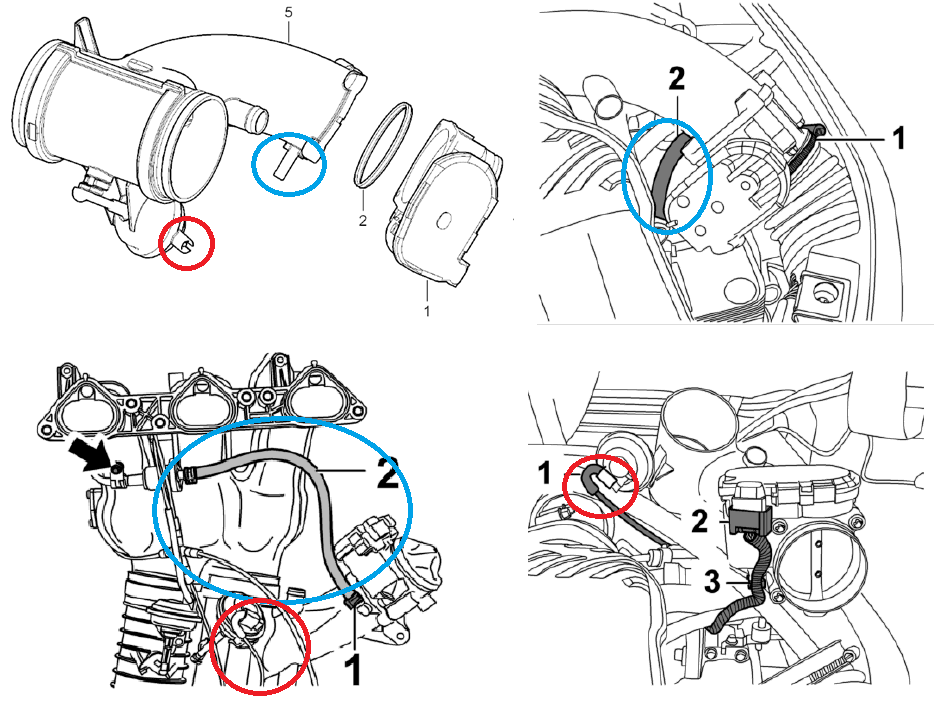
Identifying Vacuum Lines Hoses For Throttle Body Removal On 987 1 Rennlist Porsche Discussion Forums
Vacuum Diagram Help Mitsubishi 3000gt Dodge Stealth Forum

Anyone Know What These Plugged Vacuum Lines Are For 1996 150 With The 5 0 The Little Ports Underneath The Upper One Are Plugged With Bits Of Wood Truck Runs Great R Fordtrucks
Throttle Body Vacuum Line Question Toyota Rav4 Forums
Throttle Body Vacuum Lines Rennlist Porsche Discussion Forums

How To Find And Fix Vacuum Leaks Ultimate Guide Youtube
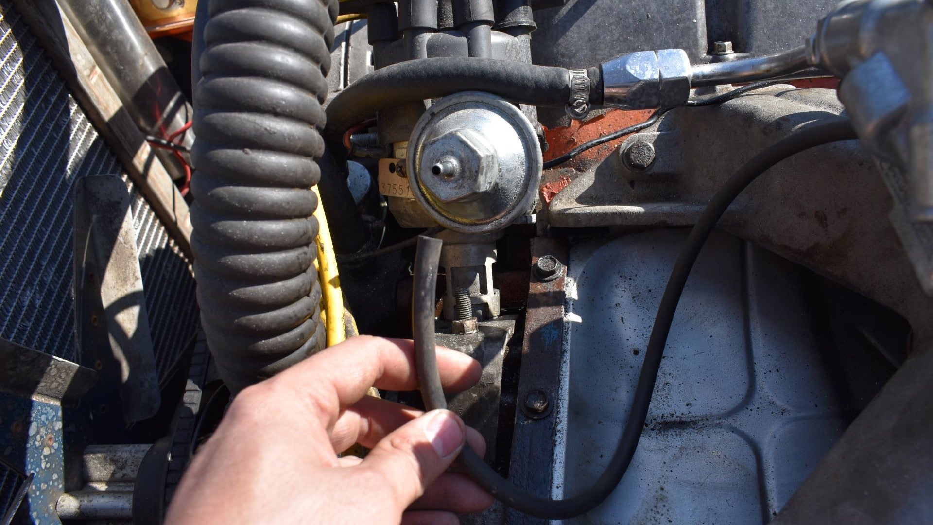
How To Check For Vacuum Leaks And Our Diy Steps To Fix Them
Ng 900 9 3 Vacuum Lines The Saab Tech Wiki

Vacuum Lines Diagrams I Got Them All Third Generation F Body Message Boards
Throttle Body Vacuum Hose End Suzuki Lt R450 Forum Ltr450hq Com
Hookup Location For Detached Hose On Throttle Body Allpar Forums

How To Test A Throttle Position Sensor Tps With Or Without A Wiring Diagram Youtube
Audizine Forums
1985 Vacuum Diagram Decal 22re Cal 4wd 59 Toyota4low
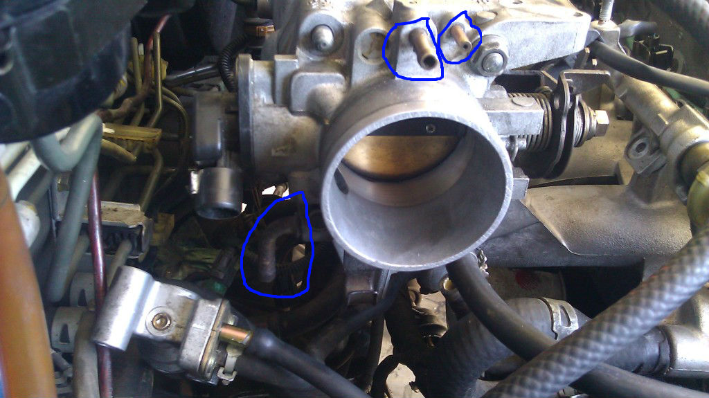
Coolant And Vacuum Hose Diagram Honda Tech Honda Forum Discussion
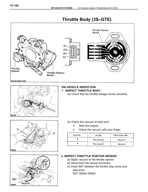
Throttle Body 3s Gte Celicatech

1988 And 1989 Vacuum Diagram Decal V6 3vze Fed U1 Toyota4low